There is no such thing as a standard solar panel size anymore. Therefore, is solar module power density (W/m2) the new efficiency comparison gauge to cut through the sales spin? Yes. And we’ve made it super easy for you to calculate, You simply need 3 variables readily available on every manufacturer’s datasheet; module length, module width and module Watts.
Contents
1.0 Contact
1.1 The Top Contact design
The top contact’s role is to let light into the cell while also transmitting electricity out. Because semiconductors, such as silicon, are orders of magnitude less conductive (and thus more resistive) than metals, a top grid pattern is required to reduce series resistance on all but the tiniest solar cells. There are translucent conductors, such as indium tin oxide, but they are less conductive than metals and absorb light.
The metal wires of the top contact should be exceedingly tiny and close together in an ideal world. However, excellent connections are prohibitively expensive in solar applications. Photolithography, for example, generates line widths of less than 1 m and is widely used in the integrated circuit industry, although it requires expensive chemicals and time-consuming alignment. Photolithography is only utilised in laboratory demonstration cells to justify the cost, and it is rarely employed in commercial cells. There is a trade-off between shading the cell, which predominantly affects ISC (Short-circuit current), and the resistance of the metal contact, which primarily affects fill factor (FF) when designing the top contact (C. H. Bowden, Top Contact Design|PVeducation n.d.).
1.1.1 Fill factor
The “fill factor” or also known as “FF” is a parameter that determines the maximum power from a solar cell in conjunction with Voc (Open-circuit voltage) and Isc (Short-circuit current). The fill factor (FF) is defined as the ratio of a solar cell’s maximum power to the product of Voc and Isc (C. H. Bowden, Fill factor | PVeducation n.d.). The higher the fill factor, the better the solar cell is (Xu n.d.).
1.1.2 Open Circuit Voltage (Voc):
Open-circuit voltage describes the maximum amount of voltage that a solar panel can generate. The current produced is 0 when there are no loads connected to the output circuit (Xu n.d.).
1.1.3 Short Circuit Current (Isc):
The short-circuit current represents the higher current that a solar panel can generate under normal testing conditions. The panel wires are linked directly in this case, indicating that the short circuit does not produce any electricity (Xu n.d.).
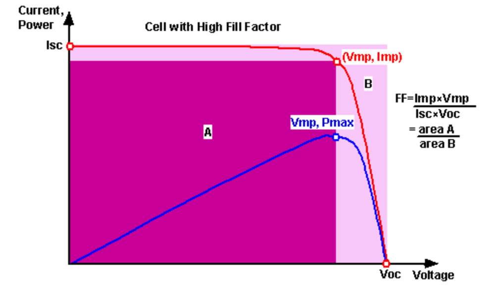
Figure 1: Cell with High Fill Factor
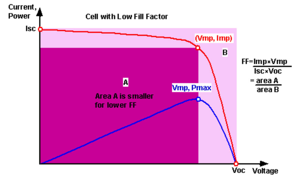
Figure 2:Cell with Low Fill Factor
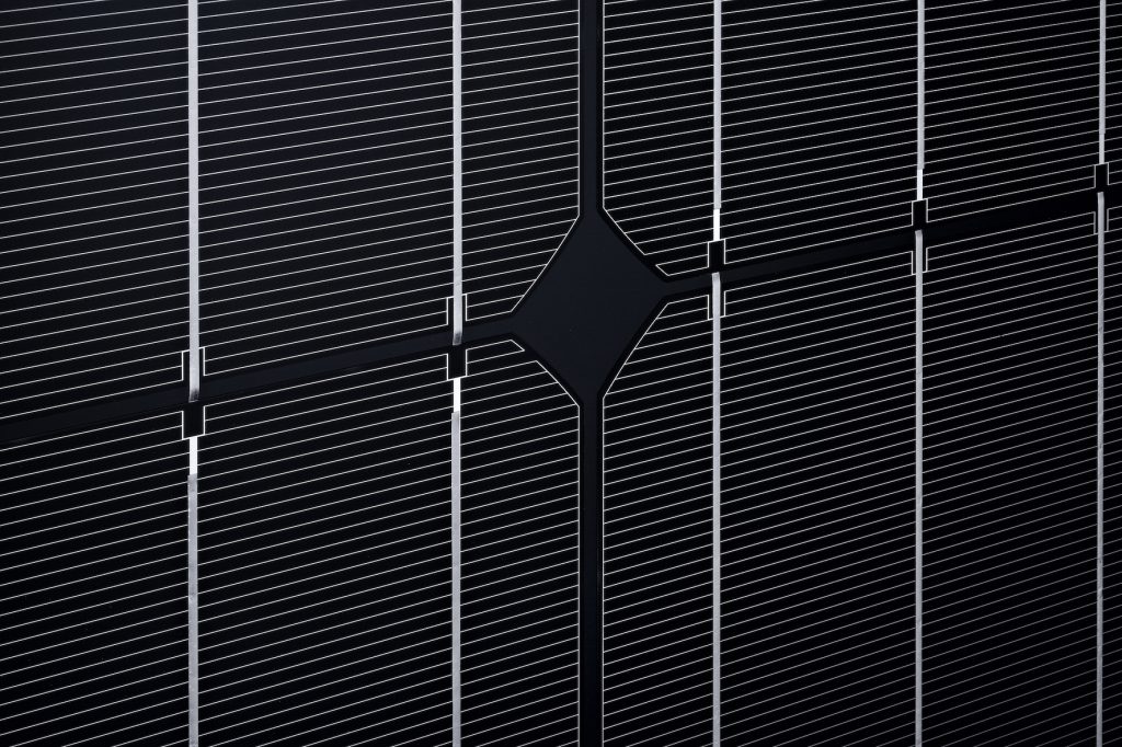
Image: Solar cell busbars are the larger metallic strips displayed vertically. Fingers are the finer lines displayed horizontally.
To collect the current generated by a solar cell, metallic top contacts are required. “Fingers” are finer sections of metallization that collect current for delivery to the busbars, while “busbars” are directly connected to the external leads. The key design trade-off in top contact design is the balance between greater resistive losses associated with a widely spaced grid and enhanced reflection generated by a large fraction of metal coverage of the top surface (C. H. Bowden, Top Contact Design|PVeducation n.d.).
1.1 Rear contact
By shifting all part of the front contact grids to the back of the device, rear contact cells can potentially achieve better efficiency. Reduced shadowing on the front of the cell may result in improved efficiency, which is especially advantageous in high current cells like concentrators or huge regions.
By placing both contacts on the back of the cell, rear contact solar cells altogether remove shading losses. Electron-hole pairs formed by light absorbed at the front surface can still be collected at the back of the cell if a thin solar cell constructed of high-quality material is used. These cells are particularly effective in concentrator applications, where cell series resistance has a higher impact. Another advantage is that cells with both connections on the back are easy to join and may be positioned closer together in the module because no space between the cells is required (C. H. Bowden, Rear Contact Solar Cells|PV education n.d.).
1.2 Multi-Busbars Contact
Solar cells are connected via busbars to provide higher voltages. The theory is that when more busbars are added, more electrons will be able to pass through, increasing power and efficiency (Pickerel 2016) .
Multi busbar cells, particularly five busbars (5BB) cells, are one of the most popular designs for solar cells and modules right now. The Multi-Busbars (MBB) approach aims to reduce resistive losses by reducing the amount of current in both the fingers and the busbars. As more busbars are printed on a wafer, the space between them shortened, shortening the current flows in the fingers, a significant source of series resistance losses. As a result of the MBB technique, both busbars and fingers can be smaller. The MBB technique can reduce silver consumption by 50% to 80%, considering silver is one of the most expensive consumables. Additionally, having less silver on the front lowers finger shading.
Busbars are typically printed flat and require soldered flat ribbons to carry current away from the cell, resulting in additional shading and resistive losses. MBBs are thin, rounded copper wires that transport electricity from the fingers to linking ribbons outside the front surface of the solar cell, eliminating the need for ribbons across the cell. Smaller rear aluminium fingers can be produced using MBB, reducing shadowing on the cell’s backside and increasing the cell’s bifacial light-harvesting function. The cell is less vulnerable to microcracks and bifacially because MBB increases the likelihood of cracked areas of the cell keeping electrical contact with the remainder of the cell (PV-Manufacturing.org n.d.) .
2.0 Enhanced
2.1 Passivation Emitter Rear Contact Cell (PERC)
The PERC architecture is not entirely new. The technology was first invoked in 1983 at the University of New South Wales in Australia. The first publication was published in 1989 (A.W.Blakers 1989). PERC solar panels initially appeared in 2012, but it took several years for manufacturers to perfect the process and lower costs (Power 2021). PERC stands for passivation emitter rear contact cell. Even though solar cell technologies such as Passivated emitter rear locally diffused (PERL), Passivated emitter rear totally diffused (PERT), and PERF was not initially included in the PERC nomenclature. However, they are now commonly regarded as members of the same family (AleoSolar 2021). PERC is a breakthrough technology that is currently available in Mono and Poly cells (RegenPower 2018).
The back surface of PERC is coated with an insulating film called the passivating layer to increase current flow. Passivation removes flaws, allowing the solar cell to produce more energy (Pamuru 2021). PERC cells are more efficient than normal cells because of this additional layer, allowing more sunlight to be absorbed and converted into power.
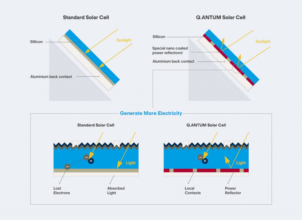
Image: Standard solar cell left. Respected QCells Q.ANTUM Passivated Emitter and Rear Cell (PERC) right.
In terms of energy production, the efficiency of a PERC solar panel is around 1% higher than that of a regular panel. This can provide up to 5% additional energy production to an entire PV system. Suppose a standard module has a 20% efficiency. In that case, a system employing PERC modules will generate around 5% more energy than a system using standard modules, assuming all other factors remain constant (Power 2021).
Other benefits of the PERC modules are that they have better flexibility. It provides end-users with more prominent tilt and positioning options while maintaining efficiency – handy for residential customers with limited roof space. Plus, lower PERC modules have lower levelized energy costs results in shorter payback times when the energy density is higher (RegenPower 2018).
2.2 Passivated Emitter Rear Totally Diffused (PERT)
PERT solar cells are one of the high-efficient solar cell technologies. PERT cells are not the same as normal cells or PERC cells. Both employ an aluminium alloy BSF, but PERT cells have a diffused rear surface. It can be applied to monofacial and bifacial solar cell designs. If properly positioned in open regions or flat rooftops, bifacial cells may collect light and generate electric energy from both surfaces, resulting in up to a 30% higher yield than standard cell technologies. The benefits of the PERT solar cells technology are:
- Passivation on many materials results in high efficiency
- Unlike PERC cells, Boron BSF PERT multi cells show no light-induced deterioration (LID).
- The cost of ownership is the same as for PERC cells.
- The PERT line can be employed for monofacial or bifacial cells, giving it much versatility. (Rooij n.d.)
2.2.1 Back Surface Field
Back Surface Field” or “BSF” comprises a highly doped region on the solar cell’s back surface. A p-n junction exists at the interface between the high and low doped regions.
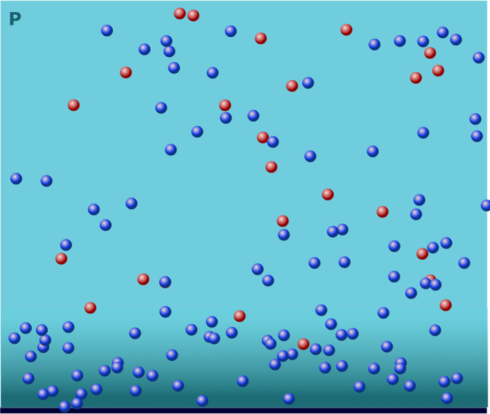
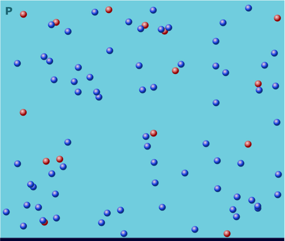
A BSF increases the voltage of a solar cell. A field is created by additional strong doping at the rear, which keeps minority carriers (in this example, electrons) away from the highly recombining rear surface. Recombination is reduced, which raises the electron concentration in the base and hence the solar cell’s voltage.
- electron
- hole
- electron
- hole
Figure 5 and 6 shows the area around the back surface field. Figure 5 shows the back surface field caused by extra heavy p-type (hole) doping which pushes n-type (electrons) away from the surface. Meanwhile, figure 6 depicts in the absence of a back surface field, minority carriers (in this example, electrons) recombine at the surface (C. H. Bowden, Surface Recombination|PV education n.d.).
2.3 Passivated Emitter Rear Locally diffused (PERL)
Passivated Emitter Rear Locally diffused or “PERL” solar cells are based on the bifacial solar cell concept and are highly efficient solar cell technologies. It also combines both PERC and PERT advantages. Both the front and back surfaces of the monocrystalline cell are passivated, while the rear is only selectively diffused at the metal contacts to reduce the recombination rate while preserving good electrical contact.
Based on n-type material, PERL cells have a long-life expectancy and a high efficiency of about 25%. Furthermore, when this efficiency is combined with the per se bifaciality of the cell architecture, up to approximately 40%, better energy efficiency can be collected and obtained in PV installations.
2.4 Bifacial solar cell
A bifacial solar cell (BSC) is a photovoltaic solar cell that can generate electricity when both its front and back surfaces are lit (Wikipedia n.d.). Solar panels that can capture sunlight from both sides are known as bifacial solar panels.
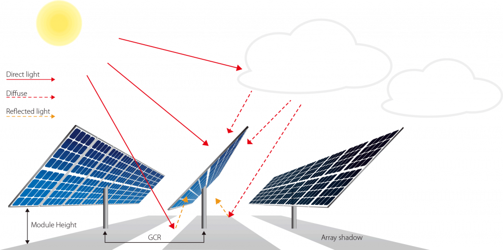
Image: LONGi Solar panels with a bifacial design are enclosed in glass and absorb sunlight reflected from the ground and adjacent surfaces.
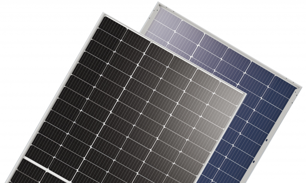
Image: LONGi HiMO-5 distinctive bifacial solar module appearance with a translucent substrate.
Bifacial solar panels function similarly to conventional solar panels. They both create power by turning light energy into electricity using the same semiconductor material. When sunlight strikes the bifacial panel, solar cells collect a portion of the light and convert it to electrical energy. Some of the light catches on the glass and is reflected throughout the panel’s interior until it lands on a solar cell and is absorbed. Some of the light shines through the glass panel and lands on the ground. This light then bounces back towards the panel and is transformed into power, assuming the ground has a high reflectance (Duval 2021).
2.4.1 Pros and Cons
Pros: Since they can catch light on two surfaces, they have better efficiency than monofacial panels. Compared to monofacial panels, many bifacial solar panel manufacturers claim that their bifacial panels produce 20% to 30% more power. Bifacial panels also perform better in diffuse light due to their larger surface area, which allows them to capture more light. This translates to reduced long-term expenses than monofacial panels. Higher efficiency also means less space required per watt, allowing homeowners to install fewer panels to meet their requirements. In addition, the tempered glass frame provides some additional advantages. The solar cells are less inclined to experience PID, which occurs when electrical currents deviate from their intended path and corrode the solar module because they do not have metal frames. The absence of plastic covering also ensures that the panel is UV resistant.
Bifacial solar panels are predicted to have longer lifespans due to their resilience and resistance to weather and various sorts of deterioration and thus have more extended warranties. The usual guarantee of a monofacial solar panel is roughly 25 years, although bifacial solar panels are frequently marketed with 30-year warranties (Duval 2021).
Cons: Bifacial solar panels are costly due to the manufacturing process. They can cost up to 10% more than monofacial solar panels, equating to an additional $20 per watt. Because bifacial panels are heavier than single-sided panels, they cost more to install due to the additional effort. They must be put on specialized equipment to take full advantage of the benefits designed to decrease shadows and optimize the albedo (the percentage of incident light or radiation reflected by a surface) of the ground around the solar panel (Duval 2021).
Bibliography
A.W.Blakers, A.Wang, A.M.Milne, J.Zhao, M.A.Green. 1989. “22.8%Efficient Silicon Solar Cell, Appl. Phys. Lett. 55 .” 1363-1365.
AleoSolar. 2021. PERC cell tecnology explained. https://www.aleo-solar.com/perc-cell-technology-explained/.
Bowden, Christian Honsberg and Stuart. n.d. Recombination Losses|PV education . https://www.pveducation.org/pvcdrom/recombination-losses.
Bowden, Christiana Honsberg and Stuart. n.d. Fill factor | PVeducation. https://www.pveducation.org/pvcdrom/solar-cell-operation/fill-factor.
—. n.d. Rear Contact Solar Cells|PV education. https://www.pveducation.org/pvcdrom/manufacturing-si-cells/rear-contact-solar-cells.
—. n.d. Surface Recombination|PV education. https://www.pveducation.org/es/fotovoltaica/design-of-silicon-cells/surface-recombination#footnote2_z2zdmc9.
—. n.d. Top Contact Design|PVeducation. https://www.pveducation.org/pvcdrom/top-contact-design.
Duval, George. 2021. Bifacial Solar Panels: What Are They And How Do They Work | Semprius. 9 November. https://www.semprius.com/bifacial-solar-panels/.
Pamuru, Rabindra Satpathy and Ventakeswarlu. 2021. Manufacturing of crystalline silicon solar PV modules. https://www.sciencedirect.com/topics/engineering/contact-solar-cell.
Pickerel, Kelly. 2016. Busbars: A solar panel necessity or hindrance?|Solar Power World. 9 May . https://www.solarpowerworldonline.com/2016/05/busbars-solar-panel-necessity-or-hindrance/.
Power, Regen. 2021. Benefits of PERC panels. 2 March. https://regenpower.com/articles/benefits-of-perc-panels/.
PV-Manufacturing.org. n.d. Multi-Busbars Solar Cells & Modules. https://pv-manufacturing.org/multi-busbars-solar-cells-modules/.
RegenPower. 2018. Why choose Mono PERC panels for your rooftop solar system? 29 December. https://regenpower.com/news/why-choose-mono-perc-panels-rooftop-solar/.
Rooij, Dricus De. n.d. PERT solar cells | SinoVoltaics. https://sinovoltaics.com/learning-center/solar-cells/pert-solar-cells/.
SolarFunda. 2021. Mono vs Mono-Perc Solar Panels: The Ultimate Guide. 10 February. https://solarfunda.com/mono-vs-mono-perc-solar-panels/.
Wikipedia. n.d. Bifacial solar cells. https://en.wikipedia.org/wiki/Bifacial_solar_cells.
Xu, Ying. n.d. Solar Cell Fill Factor Explained|SunVival guide. https://sunvivalguide.com/what-is-solar-cell-fill-factor/.


